For my custom alarm clock, I needed a light source with controllable intensity and color. It didn’t come together as easily as I expected.
For the light source itself LEDs were the obvious choice: I could get the needed brightness with a large array, and integrated red-green-blue parts are pretty common these days. In fact, arrays themselves are pretty common these days:
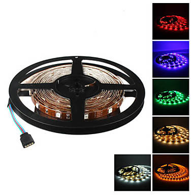
These 5-meter strips are available all over the place (I got mine from Amazon), and they’re very affordable (30 bucks, including power supply, controller, and IR remote). Evidently they’re popular for use as accent lighting. Mine was made up of ten segments soldered together, each roughly 20 inches long . I separated those and arranged eight of them in a box with a diffuser on the front, etc.; it’s all very nice. Up close the strip looks like this:
![]()
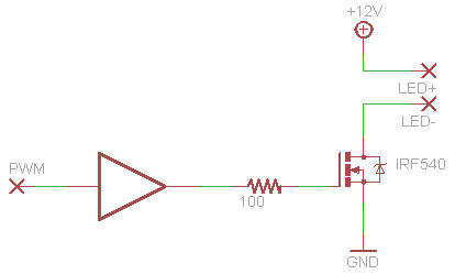
As you can see the strips are designed to be cut every three emitters (4 inches or so), and if you look closely at the cutting points you’ll see a “+12V” label. These strips are common-anode, and they have current-limiting resistors built in, so driving them should be easy. 12 volts, they’re on, no worry about delivering proper current just sufficient current. Each of the three colors has its own cathode, so switching the three colors involves getting in between the strip and ground potential. It seems simple enough: generate three PWM signals with a PIC, feed them through a buffer that can source and sink 50mA or so, and use that to drive the gates of three N-channel MOSFETs. This simple idea looks like this:
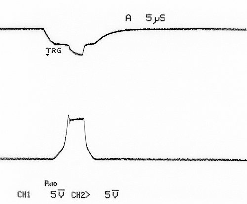
But there was one thing I hadn’t considered: the complex impedance in the circuits of 13 feet of this stuff and the consequences of switching such a thing on and off a thousand times per second. Not surprisingly 13 feet of parallel copper ribbons forms a pretty good capacitor (I measured 2nF or more between all six combinations of terminals), and who knows what kind of inductance, and when the current driving it changes suddenly it rings like a damn bell. See below: channel 1 (top) is the FET’s gate and channel 2 (bottom) is the drain.
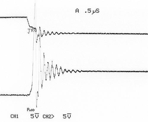
That wonderful waveform is about 45 volts peak-to-peak and about 7.5MHz. Notice the corresponding funny business at the gate. The same frequency shows up all over my circuit, even in the power supply rails.
I found a series of blog posts by Joost Damad addressing this very problem (here is the first). He was doing almost exactly the same thing: dimming a long strip of white LEDs with an N-channel MOSFET. He went out of his way to maximize the charge/discharge speed of his FET’s gate, and he then set out to reduce the consequent ringing just for “aesthetics”.
My problem was much more serious than that warm fuzzy feeling. My microcontroller, the ultimate source of the PWM signals, kept resetting. Not OK. Apparently the flyback from my LED strip was throwing my power supply around so much that it was causing the microcontroller to die even with its brown-out reset feature disabled. I had to stop the ringing or at least protect my power supply from it. Unfortunately unlike Joost I had no luck at all with simple shunt capacitors in parallel with the strip circuits. I did get some improvement with capacitor-resistor series (around 10nF+100ohm), but it wasn’t good enough. If all three PWM signals had the same duty cycle (so all three FETs switched off at the same time) the cumulative effect would still cause my microcontroller to die.
On the assumption that the core problem was that my supply voltage was being dragged around by the strip discharging, I tried adding a choke between the supply and the strip’s anode:
This did a great job of keeping the power clean, but on the open ends of the strip, at the FET drains…
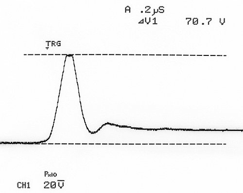
Holy shitballs. 70 (seventy) volts. That’s enough to damage the FETs. I tried putting Zener diodes to ground at the drains to head that off, but that resulted in enough energy getting back through the choke to screw up my power supply again. At this point I felt like I was just sticking fingers in holes in a dam, so I decided to take a look at the dimmer controller that came with the strip. I hoped it wasn’t a complete piece of garbage and that this issue was dealt with in some way. I hooked up the controller and turned it on, and I saw basically zero ringing. So what’s in there?

Huh. Not much. It’s practically the same circuit I’ve got: a 5V square wave driving the gate of an N-channel MOSFET with nothing much else besides a resistor. Each channel in this thing is wired like so:
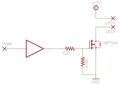
I’m not quite sure what the pull-downs are for. It’s evident from poking around with the oscilloscope that the chip generating the PWM signals is driving its outputs in both directions. Perhaps the chip’s outputs are high impedance when the device is “off”. In any case what’s important is the gate resistors. 620 ohms is surely more than the 100 ohms I was using, but it’s not quite an order of magnitude different. According to the datasheet their FETs have a bit more charge capacity in the gate than mine do, so, all in all, maybe there is an order of magnitude difference.
So, I put aside the capacitors and chokes and diodes and everything else and just put more resistance in front my gates. A lot more resistance. With 2.7K ohms in there, the gates transition much slower.
But hey, the ring is practically gone, and my power rail is solid as a rock. The microcontroller doesn’t die any more under any circumstances. Evidently the current now lets off just slowly enough to let the strip discharge.

So my solution is: just don’t slam the gates. At 960Hz and duty cycles with 10-bit resolution, the PWM signal has a resolution in time of just over 1 microsecond, so the switches really don’t have to throw completely in 40ns. The one drawback here, if I understand everything correctly, is that the slow switching causes above-nominal drain-source voltage for longer periods of time resulting in more energy lost in the FETs and more waste heat. But my parts are over-specced, they still don’t really warm up significantly, and there’s a hell of a lot more waste heat coming from the LEDs anyway. So. So be it.
Finally, if you’re curious, these are the specific parts I’m using:
- PIC16F1503 microcontroller
- 74ACT244 buffer (also 3.3V to 5V conversion)
- STP16NF06L power MOSFET


